🚀 Build, Learn, and Play with the Future of Robotics!
The MiOYOOW Soldering Practice Kit is an engaging DIY smart car project designed for students aged 10 and up. This kit teaches essential skills in soldering, electronics, and robotics while allowing users to create a customizable tracking course. With easy assembly and clear instructions, it's perfect for school science projects and promotes valuable STEM education.


| Theme | Car,Robot |
| Item Dimensions | 4 x 2.8 x 0.06 inches |
| Item Weight | 0.15 Pounds |
L**.
Neat little kit, great for starting out with electronics and soldering
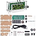
Thought I'd try this little smart car kit, I built one long ago, wasn't as nice as this one though.The kit seems small at first, everything is in a little anti-static bag perhaps 3in by 5in (8cm x 13cm?). Spread the components out and it takes up a fair bit of space. Uh, don't do that though... my cat thinks red LED's are fun to bat around.Let's see... 8 resistors, two transistors, two 10K potentiometers, 4 LED's (2 kinds of red), 2 LDR's, 2 electrolytic capacitors, 2 motors, gear sets and wheels, one battery holder (2 AA) and clicky power button. An LM393 dual op-amp, a nice blue PCB, some wire and a handful of screws. Oh, and a bolt with nut and acorn nut to work as a 'caster' wheel. Plenty to do!The kit comes with a sheet of instructions, one side has an oval track on it so you can play with your smart car right away, while the other side has instructions for assembly, a parts list and a good schematic. If you download the 'Smart Car Instruction' PDF file, it expands on the assembly instructions with good quality color photos, allowing you to visually verify you've got things in the right places, right orientation (electrolytic caps, transistors, LED's and op-amp!). Very helpful.Assembly is straightforward, start with the lowest components (the resistors, usually), and solder them to the PCB as directed, paying attention to the silkscreen for LED & eCap polarity and others as needed. I suppose it took me about an hour, I've been soldering for some years (we won't discuss how MANY years!), and it wasn't difficult at all. The possible problem areas might be the 2 pair of LED/LDR's, which are soldered on the BOTTOM of the PCB, where the solder pads are... so you're kinda soldering them in 'backwards', be sure to leave the leads long on those components so you can get your iron in under them. They need to be long anyways to shine on surface and detect reflected light (or not).The gear sets, axles, wheels and motors were fiddly to assemble, you may need three hands to keep the axle and its supports aligned while you tighten the screw on the other side of the PCB. You'll get it... but you may need to try a couple of times to get it all lined up, I did. Get one screw going good, suddenly the other axle support rotates away from its position. GRRRR! Sometimes blue-tak or masking tape can be very helpful!I have a grumble, I feel the battery holder should be installed LAST, as if you're not really careful centering it and keeping it away from other solder holes/pads, you'll have difficulty placing the four wires to power the two motors. The motor power wires must be inserted into small pads which are very close to the side of the battery holder. I'd really recommend leaving the holder until last, as you'll have more room to get your fingers, pliers, tweezers, chopsticks... whatever... in the area to connect the motor wires. Then solder the two leads for the battery holder, wrap the wires around the PCB, double-sided sticky tape the battery pack in place, and voila! Examining my car, I placed the battery holder a bit off-center (only a teensy bit!), crowding the M1/M2 motor wire contacts. just FYI.Now the really fun bit! Turning it on and tweaking the two potentiometers! This is where I'd like to have a blurb in the instructions describing the potentiometer functionality. Yes, you can figure it out by playing with them, the schematic is very helpful as you can determine that they are bias voltage level controls for the dual op-amp trigger levels. And they interact with each other a little bit, so that can frustrate a less experienced kit builder.Basically, they set the threshold for the two LDR's (Light Dependent Resistors). Depending on how much light is reflected back by the surface, the resistance of the LDR changes, changing the voltage presented to the inputs to the dual op-amp (LM393). If the voltages differ, the op-amp output either goes to Vcc or Gnd, depending in which voltage is higher (wikipedia has a good article on op-amps, check it out). If the output is low (Gnd), it turns on its appropriate transistor and energizes a motor. If the output is high (Vcc), it turns OFF the transistor (PNP) and the motor is de-energized, stopping it.You'll have to tinker with the potentiometer settings to get Mr Smart Car to behave, My experience thus far is to start both pots at dead center, and with the power on, tweak them every so very very slightly CCW (counter-clockwise). My car likes to go to the right preferentially, sometimes I can get it to go left... but generally he likes going around the track in a clockwise direction. Your experience will likely vary from mine. You'll swear it has a mind of it's own though.I took mine into work and set up a huge track using electrical tape on a large table. It ran for several hours with people picking it up and looking, then putting it down to zoom around again. We all had fun!I've enjoyed the kit and will likely order more to give to my friends and their kids, perhaps I can spark their interests in electronics. Or maybe a smart car racing club!
B**L
A fun line following robot kit that works well.
The media could not be loaded. I bought this Line Following Robot Kit for my 13 year old son and myself to put together. He likes technology and enjoys watching things work, and when I showed him the kit on Amazon he was very excited to receive and build it. While I’ve assembled many kits over the years, I think this was either the fourth or fifth kit he’s put together.The kit arrived on time and in good shape. It was shipped from Amazon in a padded envelope, and is contained within two bags – one clear, one silver colored. I was very impressed to receive an e-mail from the seller through Amazon’s messaging system with a link to a PDF assembly manual. The manual is very thorough – 16 pages long and has lots of nice, clear photos that are annotated with instructions. The kit components are good quality and it comes with a little “test track” that I show in the photos and video.The kit went together well – there are a few places where it took us a bit of time as the parts are small, but nothing we couldn’t handle. The photos in the manual are a big help in putting the kit together. My son soldered most of the components himself without any problems. I did solder the photoresistors and LEDs on the bottom, as the leads were close together and it took a little bit of trial and error to get the photoresistor and LED heights correct.As can be seen in the video, the line following robot works pretty well! We built up a bigger tracking using the electrical tape suggested in the instructions on a piece of cardboard. The electrical tape worked very nicely and we were able to make a much bigger track for the robot to follow. The electrical tape we used was slightly rubbery, so the robot moved slower due to the front support having more friction from the electrical tape than just plain paper. Our pet cats were very intrigued by this little robot running around the cardboard test track. One of them was walking by the edge of the track and the robot kept nudging him along almost like it was herding him! It was pretty funny.We found the robot to be quite durable – while I was trying to set up my phone to take a video, it accidently drove off the track (the track isn’t perfect and had a bad spot) and fell onto the floor, a height of several feet. The batteries did pop out of the battery holder, but there was no damage to the robot.Bottom line, this is a lot of kit for very little money – a really great value, fairly easy to assemble, and works well. Both my son and I were very pleased with it.
A**Y
Low Parts Count for an Easy Teaching Tool
Taught my daughters, 5 and 7, component identification, soldering skills, safety, and fun with these kits! Both girls had an absolute blast bending leads and placing parts, and when it came time to solder, they ran the iron while i applied the solder.Minus one star, as the Instructions are only single page with the schematic and parts list on one side and an oval track on the other. I had to refer to the product listing several times during mechanical assembly to ensure proper fitment.A great time was had by all.
Trustpilot
3 weeks ago
1 week ago